WEG CFW11 Variable Speed Drive
This guide will show you how to connect the Polar Monitoring Gateway to the WEG CFW11 Variable Speed Drive. It will also take you through the setup and parameters required on the WEG CFW11 to ensure communications to the Polar Gateway.
Steps to follow:
- Connect power to the Gateway.
- Connect RS-485.
- Final checks.
- Power on the system.
- Configure the CFW11 Serial Parameters.
WEG CFW11 Connection Setup
1. Connect power to the Gateway.
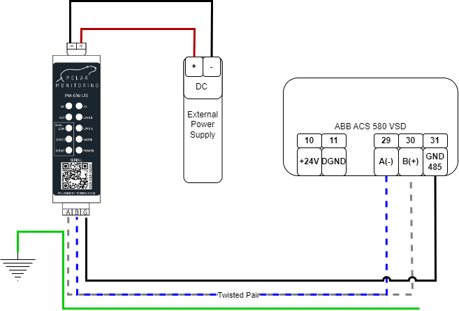
A. Power the gateway from an external power supply.
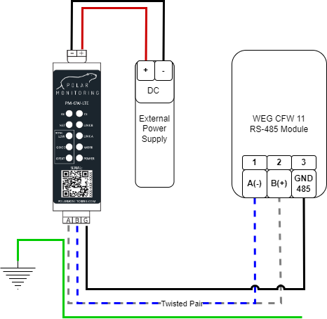
Wire the Polar Gateway to a 12-24 V DC power supply. Connect the positive wire to the positive terminal and the negative wire to the negative terminal.
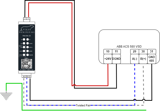
B. Power the gateway from the VSD.
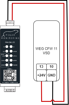
Wire the Polar Gateway directly to the VSD. Connect the positive wire to the +24V(13) terminal and the negative wire to the GND(10) terminal.
2. Connect RS-485.
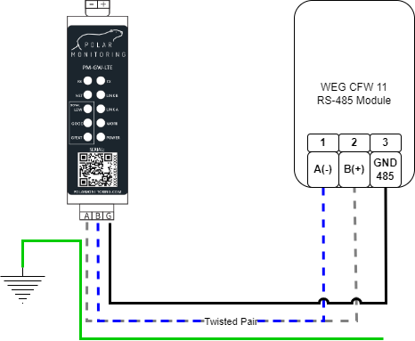
Wire the RS-485 cable to allow communication with the Polar Gateway.
Connect A+ => B+ (1) and B- => A- (2).
Please note the missatch on (A) and (B), Follow the (+) and (-) lables. What is RS-485?
3. Final checks
- Make sure the wiring is secure – no short circuits.
- Ensure that all connections are secure on the device and the gateway.
- Re-check the RS-485 twisted pair cable is correctly wired.
- Check that the A and B are correctly wired to the device.
4. Power on the system
Now you are ready to go, you can now switch on the Polar Gateway and the WEG CFW11.
5. Configure CFW11 Serial Parameters
Note: It is critical to change the default settings to reflect the table below.
Serial Communication Setup
Below is the basic set of parameters needed inorder to get serial communications working. This should allow you to see data & be able to program the device remotely.
| Name | Description | Parameter | Default | Required |
| Serial Address | Serial Slave ID | P0308 | 1 | 1 |
| Serial Baud Rate | Baud Rate | P0310 | 0=9600 | 0=9600 |
| Data Format | Communication settings | P0311 | 3=8bits,no,2 | 0=8bits,no,1 |
| Serial Protocol | Modbus Communication protocol | P0312 | 2=Modbus RTU | 2=Modbus RTU |
Remote Control Setup
Modbus registers can be edited and monitored remotely, but to enable remote control of the variable speed drive the below registers must be set accordingly.
| Name | Description | Parameter | Default | Required |
| LOC/REM Selection Src | What source will determine if the device is in REM/LOC mode. (set =1, to force drive into remote mode). | P0220 | 2 | 1 |
| REM Reference Sel. | Speed / frequency reference source when in remote mode. | P0222 | 0 | 9 |
| REM Run/Stop Sel. | Start/Stop Command Source when in remote mode. | P0227 | 0 | 2 |
You may now sign in to the Polar Portal to monitor the device remotely, the button on the right will take you through a setup process.