How can we help?
< All Topics
Print
Growcol MPS Inverter – EMS
PostedMarch 18, 2024
UpdatedMarch 28, 2024
ByJarod Lesser
This guide will show you how to connect the Growcol MPS Inverter to the EMS Panel. It will also take you through the setup and parameters required on the inverter to ensure communications to the EMS Panel are successful and to monitor and manage your device remotely.
Steps to follow:
- Growcol MPS Setup.
- Configure the Growcol MPS Parameters.
- Continue with Cloud Setup
* The Growcol MPS can be connected to the EMS panel using Modbus TCP or Modbus RTU, we highly recommend using Modbus TCP. Below you are shown how to connect the panel both ways.
1. Growcol MPS Connection Setup
A. Connecting the Growcol MPS to the EMS panel using Modbus TCP.
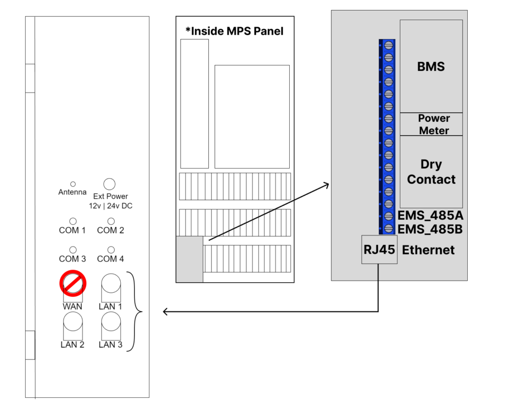
- Wire the MPS RJ45 port into either LAN1, LAN 2, or LAN 3 of the EMS Panel with a shielded CAT 5e or better ethernet cable.
- NB!! Ensure that there is an ethernet cable connected into the inverter’s HMI
B. Connecting the Growcol MPS to the EMS panel using Modbus RTU
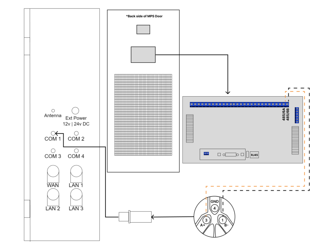
- Wire MPS Inverter RS485-6A into RS-485 Connector Pin A+ (3).
- Wire ATESS Inverter RS485-6B into RS-485 Connector Pin B- (1).
2. Configure the Growcol MPS Parameters.
A. Parameter Setup for Modbus TCP
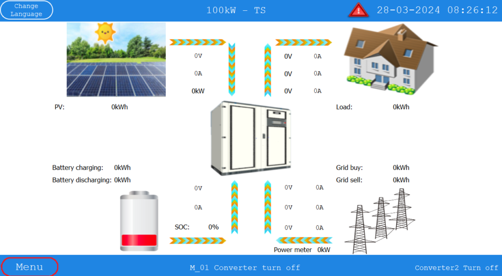
- From the Home Screen, select the Menu button.
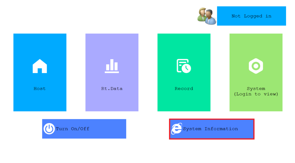
- In the Menu screen, select System Information.
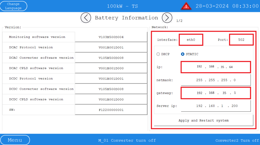
- In the System Information Menu, ensure the parameters are as follows:
IP Address: 192 . 168 . 35 . 64 Gateway: 192 . 168 . 35 . 1 Interface: eth0 Port: 502 - NB!! If there are multiple inverters, increment the IP address by one for each additional inverter, e.g:
- Inverter 1 = 192.168.35.64
- Inverter 2 = 192.168.35.65
- In this case you will need to insert inverter 2 into another LAN port on the EMS Panel.
B. Parameter Setup for Modbus RTU
- Please ensure that the Modbus RTU parameters are as follows:
Slave ID: 20 Baud Rate: 9600
3. Continue with Cloud Setup.
Now that you have successfully connected your device, you can continue to setting up the device on the cloud.
Table of Contents