Veikong VFD-500-PV Solar Inverter
This article describes the connection and setup of the Veikong VFD-500 Solar Inverter, to the Polar Monitoring Gateway.
Steps to follow:
- Connect power to the Gateway.
- Connect RS-485.
- Final checks.
- Power on the system.
- Configure the Veikong VFD-500-PV Solar Inverter Serial Parameters.
Veikong VFD-500-PV Solar Inverter Connection Setup
1. Connect power to the Gateway.
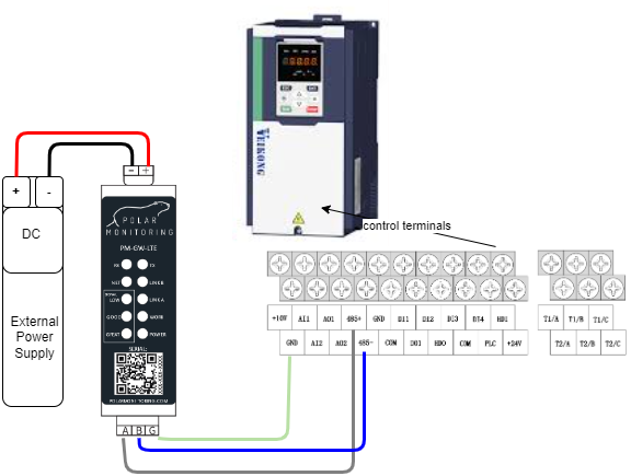
A. Power the gateway from the external power supply.
Wire the Polar Gateway to a 12-24 V DC power supply. Connect the positive wire to the positive terminal and the negative wire to the negative terminal.
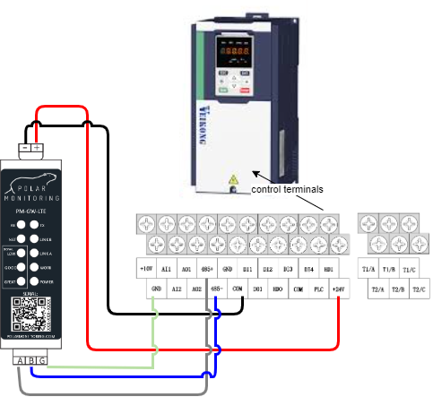
B. Power the gateway from the Veikong VFD-500-PV Solar Inverter.
Wire the Polar Gateway directly to the VSD. Connect the positive wire to the (+24V) terminal and the negative wire to the (COM) terminal.
2. Connect RS-485.
Wire the RS-485 cable to allow communication with the Polar Gateway. Connect A+ to 485+terminal,B- to 485- and G to GND.What is RS-485?
3. Final checks
- Make sure the wiring is secure – no short circuits.
- Ensure that all connections are secure on the device and the gateway.
- Re-check the RS-485 twisted pair cable is correctly wired.
- Check that the A and B are correctly wired to the device.
4. Power on the system
Now you are ready to go, you can now switch on the Polar Gateway and the Veikong VFD-500-PV controller.
5. Configure Veikong VFD-500-PV Serial Parameters
Serial Communication
| Name | Description | Parameter | Default | Required |
| Serial Address | Serial Slave ID | P30.01 | 1 | 1 |
| Serial Baud Rate | Baud Rate | P30.02 | 3 = 9600bps | 3=9600bps |
| Serial Bytes Config | Communication settings | P30.03 | 0 = 8 bits, no,1 | 0 = 8 bits, no, 1 |
Serial Protocol | Communication Protocol | P30.00 | 0=Modbus | 0=Modbus |
Remote Control Setup
| Name | Description | Parameter | Default | Required |
| Operation Command Source (AUTO, REMOTE) | Determines the operation frequency source in the “AUTO, REMOTE” mode. | P00.06 | 0 | 2 |
| Master Frequency Command Source (AUTO, REMOTE) | Determines the master frequency source in the “AUTO, REMOTE” mode. | P01.00 | 0 | 7 |
You may now sign in to the Polar Portal to monitor the device remotely, the button on the right will take you through a setup process.