How can we help?
< All Topics
Print
ATESS Inverter – EMS
PostedJanuary 16, 2024
UpdatedFebruary 6, 2024
ByJarod Lesser
This guide will show you how to connect the ATESS Inverter to the EMS Panel. It will also take you through the setup and parameters required on the inverter to ensure communications to the EMS Panel are successful, in order to monitor and manage your device remotely.
Steps to follow:
- ATESS PCS 250 Connection Setup.
- Configure the ATESS Parameters.
- Continue with Cloud Setup.
1. ATESS PCS 250 Connection Setup.
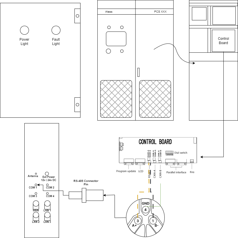
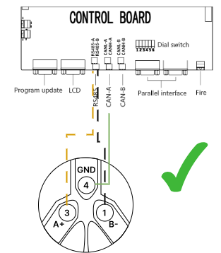
A. Connecting RS-485 from the inverter to the RS-485 Connector Pin
- Wire ATESS Inverter RS485-A into RS-485 Connector Pin A+ (3).
- Wire ATESS Inverter RS485-B into RS-485 Connector Pin B- (1).
B. Connecting the RS-485 Connector Pin to the EMS panel.
Once you have wired the ATESS into the RS485 connector, plug the connector into the COM1 port on the side of the panel.
2. Configure the ATESS Parameters.
It is important that the parameters on the ATESS are set correctly so that the EMS panel can control and monitor the inverter correctly.
| Parameter | Required |
| Slave ID: | Unique Slave ID |
| Baud Rate: | 9600 |
3. Continue with Cloud Setup.
Now that you have successfully connected your device, you can continue to setting up the device on the cloud.
Table of Contents